Recently I’ve had a query from a customer about host that generates traffic and affects link utilization between two data centers. Customer has Layer 2 networks spanned across DCs connected with one physical link between Cisco core switches, ports for the link are configured as trunks and they are passing through several VLANs.
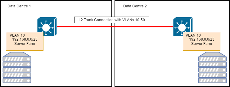
DC interconnect
The task at first seemed pretty obvious – just look into Netflow statistic reported by core switches and provide it to customer, however nothing is being simple in this world :), – unfortunately NetFlow data was not available(not configured on the switches and due to change management procedures in place we can’t just switch it on straight away).To identify who is an offender I followed four simple steps:
Step 1 – Finding the most saturated interface
Look at overall link utilization between DCs, luckily for me this customer has fairly small traffic on most of VLANs between DCs(otherwise my trick may not work, see below).
Utilization on the concerned link between DCs:
DC1SW01#sh int gi1/1/1 | in rate|is up
Queueing strategy: fifo
5 minute input rate 1957000 bits/sec, 1625 packets/sec
5 minute output rate 147768000 bits/sec, 12474 packets/sec
Step 2 – Finding interface with mirrored traffic
But it does not help to find the source of that traffic.. Most likely traffic has a single source(as it was suddenly generated as per customer’s words), so we should have another port on the switch with almost mirrored input and output rates, keep in mind that if you have lots of traffic on other VLANs spanning trunk connection this may not work for you.
And here it is:
DC1SW01#sh int gi1/0/1 | in rate|is up
Queueing strategy: fifo
5 minute input rate 148876000 bits/sec, 12464 packets/sec
5 minute output rate 927000 bits/sec, 1502 packets/sec
Step 3 – Tracing actual offender
Now we can trace offender further:
The only host behind gi1/0/1 is with MAC address:0000.1111.2222
DC1SW01#sh mac address-table int gi1/0/1
Mac Address Table
——————————————-
Vlan Mac Address Type Ports
————— ————-
10 0000.1111.2222 DYNAMIC Gi1/0/1
Total Mac Addresses for this criterion: 1
Step 4 – Mapping MAC to IP
Determine IP address:
DC1SW01#sh ip arp vlan10 | in e41f.13bf.833c
Internet 192.168.0.121 27 0000.1111.2222 ARPA Vlan10
Same steps could be done on the core switch in DC2 to trace second leg of the traffic flow.
Hope this post helps someone to save some time troubleshooting similar issue with lack of data sources.